ARS6-SS – 316 Stainless Steel Compression Struts
Stainless Steel – Stainless steel G316 tubes: BS EN10296-1
| Fork/Bar Sizes | M12 | M16 | M20 | M24 | M30 | M36 | M42 | M48 | M56 | ||||
| CHS Size | |||||||||||||
| (Dia. x t mm) | 1.327 x 0.157 | 1.661 x 0.157 | 1.902 x 0.197 | 2.374 x 0.197 | 2.996 x 0.197 | 3.5 x 0.197 | 4.5 x 0.248 | 5.5 x 0.394 | 6.626 x 0.394 | ||||
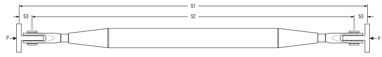
| S1 (ft) | P — Design Resistance in kip | ||||||||||||
| 4.921 | 1.348 | 4.045 | 8.765 | 17.529 | 35.732 | 60.678 | 85.848 | 95.736 | 173.493 | ||||
| 6.562 | 2.697 | 5.843 | 10.787 | 27.642 | 58.655 | 85.848 | 95.736 | 173.493 | |||||
| 8.202 | 2.247 | 4.270 | 7.866 | 18.877 | 40.002 | 85.848 | 95.736 | 173.493 | |||||
| 9.843 | 3.596 | 6.068 | 14.608 | 29.889 | 64.498 | 89.893 | 173.493 | ||||||
| 11.483 | 2.922 | 5.169 | 11.911 | 24.046 | 49.891 | 87.196 | 173.493 | ||||||
| 13.123 | 2.697 | 4.495 | 10.113 | 20.226 | 40.677 | 73.487 | 142.930 | ||||||
| 14.764 | 2.247 | 3.820 | 8.765 | 17.529 | 34.609 | 61.801 | 117.535 | ||||||
| 16.404 | 3.596 | 7.866 | 15.057 | 30.114 | 53.262 | 99.107 | |||||||
| 18.045 | 3.146 | 7.191 | 12.360 | 26.743 | 46.744 | 85.623 | |||||||
| 19.685 | 2.697 | 6.068 | 10.113 | 24.271 | 42.025 | 75.510 | |||||||
| S3 (mm) max | 1.969 | 1.969 | 1.969 | 2.953 | 3.937 | 3.937 | 3.937 | 4.921 | 4.921 | ||||
| Minimum assy lengths | |||||||||||||
| S2 (mm) min | 11.65 | 13.78 | 15.51 | 17.87 | 21.34 | 24.17 | 28.58 | 32.28 | 37.48 | ||||
| The data supplied is appropriate for inclusion in the relevent design calculations | |||||||||||||
Partial factors
The allowable loads refer to the minimum design resistance in KN, calculated using the UK National Annex, material and Load Factors.
| Partial factors for design of building members/sections EN1993-1-1 | ||||||||
| YM0 | YM1 | YM2 | YM3 | YM4 | YM5 | YM6 | YM7 | |
| 1 | 1 | 1.1 | 1.25 | 1.1 | 1 | 1 | 1 | |
| Partial factors for design of building connections/joints EN1993-1-8 | ||||||||
| YM0 | YM1 | YM2 | YM3 | YM4 | YM5 | YM6 | YM6,ser | YM7 |
| 1 | 1 | 1.25 | 1.25 | 1.1 | 1 | 1 | 1 | 1.1 |


