Space. Simple form. Both mask a complexity inherent in tensile architecture. The structure in place, itself evidence of science and careful planning, stands to remind us of what can be achieved with the intelligent use of rods working together in tension.
Be it a glazed curtain wall, a suspended roof structure, a simple yet elegant suspension bridge, or a cable net or grid structure, all can depend on rods as the primary load carrying elements. The results are structures of unique depth and openness, with large spans made possible by balancing the need for reduced self weight, with the application of minimalist and efficient high tensile rod tendons. This is lightweight tensile architecture and a Ronstan passion.


Description
A compact stainless rod system with optimal aesthetics, efficiency and performance.
Lengths/Span
Up to 4.0m (13.1ft) for ø 6.4-15.9mm (0.252-0.626in.)
Up to 6.0m (19.7ft) for ø 19.1-31.8mm (0.752-1.252in.) before joiners are required.
Rod Diameters
6.35mm (0.250in.) to 32mm (1.252in.).
Specific Features
- Minimalist design ensures compact neat details.
- Easy adjustment of the rod from one end enables simple access and fast installation reducing time on site.
- No exposed threads ensuring the ‘sleekness’ of the rod is carried through the entire system.
- Clean polished stainless steel finish to withstand the harshest environments.
- Good strength to weight ratio allows the mass of your structure to be kept low while minimising material and transport costs.
- High corrosion resistance and low maintenance due to material choice decreases the life cycle cost of the structure.
- Range of surface finishes – #7 Polished and passivated (standard option),
#4 Satin. Others by request.
| Mechanical Properties | Ø 6.4 – 12.7mm | Ø 15.9 – 31.8mm |
| (Ø 0.252 – 0.374 in.) | (Ø 0.500 – 1.252 in.) | |
| Minimum Yield Stress | 310 N/mm² | 205 N/mm² |
| Minimum Breaking Stress | 620 N/mm² | 515 N/mm² (74,690 psi) |
| Minimum Elongation | 30% | 30% |
| Modulus of Elasticity | 193 kN/mm² (27,992 ksi) |
193 kN/mm² (27,992 ksi) |
| Material to | ASTM A276-A | ASTM A276-A |

Description
A stainless rod solution for large diameter high load applications.
Lengths/Span
Up to 6.0m (19.7ft) for ø M12 – M16 (0.472-0.630in.)
Up to 7.5m (24.6ft) for ø M20 – M42 (0.787-1.654in.)
Up to 6.0m (19.7ft) for ø M48 – M56 (1.890-2.047in.)
before joiners/turnbuckles are required.
Rod Diameters
M12 (0.472in.) to M56 (2.047in.) as standard. Larger sizes available on request.
Specific Features
- Attractive tapered nut and recognisable “tear drop” fork for a simple elegant style that will not date.
- Simple connection detail of pin and fork minimising installation time.
- Satin finish stainless steel for a modern aesthetic. Other finishes available on request.
- Large range of diameters available to allow consistent detailing throughout a project.
- Austenitic material.
| Mechanical Properties | M12 – M42 | M48 – M56 |
| (Ø 0.472 – 1.654 in.) | (Ø 1.890 – 2.047 in.) | |
| Minimum Yield Stress | 520N/mm² (75.400psi) |
460N/mm² (66,700 psi) |
| Minimum Breaking Stress | 650 N/mm² (94,300psi) |
610N/mm² (88,400 psi) |
| Minimum Elongation | 19% | 19% |
| Young’s Modulus | 193 kN/mm² (27,992 ksi) |
193 kN/mm² (27,992 ksi) |
| Material to | EN 10283 / EN 10088 BS970 |
EN 10283 / EN 10088 BS970 |

Description
A simple and effective stainless rod for moderate loads
Lengths/Span
Up to 4.0m (13.1ft) for ø 4.76-15.88mm (0.188-0.625in.)
Up to 6.0m (19.6ft) for ø 19.00-31.75mm (0.750-1.250in.)
before joiners are required
Rod Diameters
4.76mm (0.188in.) to 31.75mm (1.250in.)
Specific Features
- Most economical solution when the good level finish of stainless steel is required, providing affordable good looks.
- ARS3 – the perfect marriage of economy, strength and corrosive resistance.
- The proven design provides ageless integrity to your structure.
- 316 grade stainless steel, utilising cold drawn bar material with 94% average recycled content*.* Source: UGITECH, France.
| Mechanical Properties | Ø 4.76 – 12.70mm | Ø 15.90 – 31.75mm |
| (Ø 0.188 – 0.375 in.) | (Ø 0.500 – 1.250 in.) | |
| Minimum Yield Stress | 310 N/mm² | 205 N/mm² |
| Minimum Breaking Stress | 620 N/mm² (98,600 psi) |
515 N/mm² (74,690 psi) |
| Minimum Elongation | 30% | 30% |
| Modulus of Elasticity | 193 kN/mm² (27,992 ksi) |
193 kN/mm² (27,992 ksi) |
| Material to | ASTM A276-A | ASTM A276-A |

Description
An attractive carbon steel rod system of unparalleled tensile strength
Lengths/Span
Up to 6.0m (19.7ft) for ø M12-M16mm (0.472-0.630in.)
Up to 12.0m (39.4ft) for ø M20-M100 (0.787-3.937in.)
before joiners are required
Rod Diameters
M12 (0.472in.) to M100 (3.940in.)
Specific Features
- Highest load capacity reducing the mass of your structure with flow on benefits in transport and construction costs.
- Large range of sizes to allow consistent detailing throughout a project.
- Galvanised, raw or primed finish allows for on site paint matching to structure colour and finish.
- Attractive tapered nut and recognisable “tear drop” fork for a simple elegant style that will not date.
- Simple connection detail of pin and fork minimising installation time.
- A fine grain micro alloyed carbon steel which is fully weldable.
| Mechanical Properties | M12 | M16 – M100 |
| (Ø 0.472 in.) | (Ø 0.630 – 3.940 in.) | |
| Minimum Yield Stress | 355 N/mm² (51.490psi) |
520 N/mm² (75,400 psi) |
| Minimum Breaking Stress | 610 N/mm² (88,400psi) |
650 N/mm² (94,300 psi) |
| Minimum Elongation | 20% | 19% |
| Young’s Modulus | 205 kN/mm² (29,700ksi) |
205 kN/mm² (29,700 ksi) |
| Material to | EN 10025 | EN 10267 |

Description
Compression struts for structural design in steel and timber construction
Lengths/Span/Threads
Wide range of sizes, load values & resulting span lengths
Threads Stainless Steel M12 to M56 (0.472” – 2.205”)
Carbon steel M12 to M100 (0.472” – 3.940”)
Threads to BS3643
See table for general load / length data
Adjustment range – All compression struts are supplied fully assembled and set to the nominal pin-pin length. The installed strut can be adjusted to length by +/- 50 mm.
Strut Diameters
Carbon steel – up to 12m (39.4ft) length
Stainless steel – up to 6m (19.6ft) length
* subject to available CHS stock availability
Specific Features
- Range of adjustable compression struts to complement our existing tensile threaded bar systems.
- A compression strut comprises a central tubular section with a welded cone at either end and a threaded fork and pin end.
- End fittings are the same style as ASR2 & ARS4 end fittings for common appearance throughout a specific project.
- All threads concealed under adjustable end fittings.
- Standard compression strut systems are available in both Carbon steel and Stainless steel.
- The Carbon steel system can be supplied as raw steel, hot dip galvanised or blast / primer painted for final top coat.
- The Stainless steel system is supplied standard with a satin polish, other finishes available upon request.
- Structural design service of compression strut systems available.
- Please contact us for Structural design assistance with your project details and for pricing.
- Certified to Execution Class 2 (EXC2) BS EN 1090-2:2008 + A1:2011
| Typical Specification Examples |
| Ronstan ARS6-CSM30 Carbon steel compression strut 76.1 x 5 CHS Raw – 3500mm pin to pin length Qty 10 |
| Ronstan ARS6-GSM42 Carbon steel compression strut 114.3 x 5 CHS Galvanized 2550mm pin to pin length Qty 4 |
| Ronstan ARS6-PSM42 Carbon steel compression strut 114.3 x 5 CHS Painted 10500mm pin to pin length Qty 2 |
| Ronstan ARS6-SSM20 Stainless steel compression strut 48.3 x 5 CHS – Satin #4 6ft 4inch pin to pin length Qty 20 |
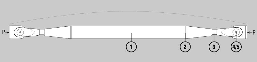
Basic Principals
-
- A compression strut comprises a central tubular section with a threaded taper connection welded at each end.
- The taper connection is assembled with a threaded fork/pin end connection and threaded lock cover.
- The threaded fork end connection enables the compression strut to be adjusted in length. The nominal strut adjustment length is +/- 50 mm.
- The tapered lock cover and machined cone conceal the threads.
- The installed compression strut is fixed to the final length by use of a grub screw set into the cone.
- The strut system is designed in accordance with EN1993-1-1 and
- EN1993 -1-8 and their respective UK National Annexes.
- The ultimate capacities quoted take account of self-weight bending of the strut in accordance with equation 6.10, Table NA.A1.2(B) UK National Annex to EN1990.
| Critical Sections |
| 1 CHS Verification Section Capacity (combined bending & axial) |
| 2 Interface between CHS & Welded Cone Weld size required |
| 3 Threaded Bar Combined bending & axial Axial resistance of thread |
| 4 Fork Combined bending & axial (major axis only) |
| 5 Pin Combined Bending & Shear NB: Reference to ‘bending’ above means the summation of strut buckling and self-weight bending effects. All material factors are as the UK National Annex. |


